
Development of Bus and Line Control Method for Short-Circuit Current Reduction Using Genetic Programming


Department of Electrical Engineering, Gachon University, 1342, Seongnamdaero, Sujeong-gu, Seongnam-si 13120, Korea
*
Author to whom correspondence should be addressed.
Energies 2022, 15(3), 678; https://doi.org/10.3390/en15030678
Submission received: 25 November 2021
/
Revised: 2 January 2022
/
Accepted: 14 January 2022
/
Published: 18 January 2022
(This article belongs to the Special Issue Fault Current Limiters: Technologies, Applications and Field Experience)
Abstract
:In this study, genetic programming (GP) is used for optimizing bus and line separation methods to reduce the short-circuit current. Expanding power systems led to intensive electric power and more transmission lines, reducing the grid impedance. This increases the short-circuit currents that occur during failure, and it is impossible to continue developing higher-capacity breakers to accommodate such short-circuit currents. Therefore, the short-circuit currents must be managed systematically through busbar separation and line separation. However, there are countless possible bus and line separation schemes for power systems. Furthermore, to comply with power-system reliability standards, no lines or transformers should be overloaded after such controls are applied. This paper proposes the use of GP to optimize the bus and line separation methods for obtaining a solution. The solutions are limited to methods that can be implemented in real power systems, reducing the convergence probability and optimization time. The proposed technique is useful for designing power systems with consideration of the short-circuit current.
1. Introduction
The demand for electricity in South Korea is increasing rapidly owing to economic growth and improvement in living standards, and this is accompanied by a large increase in the power output. In particular, the power generation on the east coast will increase from 8.2 to 18 GW, and that on the west coast will increase from 6.5 to 10 GW [1]. The power output is becoming more highly concentrated in coastal regions. However, the load is becoming increasingly concentrated in metropolitan areas. Therefore, the power generation and the load are regionally unbalanced.
The geographical imbalance of the power generation and load necessitates large-scale long-distance transmission. Accordingly, power facilities such as transmission lines and transformers must be expanded for large-scale transmission. As the number of power facilities increases, the stability of the power system increases. Because the transmission impedance of the grid is reduced, the transmission loss is reduced, and accordingly, the voltage stability and transient stability of the grid are improved.
However, when the transmission impedance decreases, the magnitude of the short-circuit current increases. This phenomenon commonly results from the concentration of power generation and the overcrowding of cities as the scale of the power system increases. In this case, the short-circuit current becomes higher than expected, and if left as is, it cannot be cut off at the current level of circuit breaker development. In fact, when all Korea Electric Power Corporation (KEPCO) systems are integrated and operated without busbar separation controls or line separation controls, the short-circuit current of the 154 kV bus increases to a maximum of 187 kA, and the short-circuit current of the 345 kV bus increases to a maximum of 86 kA [2]. Because the maximum current of the circuit breakers developed thus far is 80 kA, both 345 and 154 kV are insufficient to block the short-circuit current. Moreover, even if a circuit breaker with a higher current is developed, it will be too large to install easily.
Thus, the short-circuit current of the power system must be managed in a planned manner. Various methods can be used to reduce the short-circuit current. The most widely used methods are busbar separation control and line separation control [3,4,5]. In the case of busbar separation and line separation, there is no additional cost, because existing facilities are used, and only the operation method is changed. However, because busbar separation and line separation do not arbitrarily use the equipment installed in the system to reinforce the power system, an overload on nearby lines and transformers may occur. Moreover, this method has the disadvantage of reducing the stability of the system. Nevertheless, it is the most commonly used method for reducing the short-circuit current, because it is fast and inexpensive. Additionally, there is a method of dividing the system using the “splitting” function, which cuts the system with a ring-bus configuration in an optimal manner [6,7,8]. This method, which considers the number of breakers needed to divide the system, is the most economical method for isolating the short-circuit current. However, in this plan, the economic feasibility was mainly considered, and it was not judged whether the short-circuit current was reduced, or whether the nearby lines and transformers were overloaded. Additionally, in performing “splitting”, only the results obtained through repeated execution were presented, not those obtained using computational techniques, e.g., reflecting impedance.
Another traditional method for reducing the short-circuit current is to install a current-limiting reactor to forcibly increase the line impedance. The current-limiting reactor increases the impedance of the system by inserting an inductor (L) component in series in the transmission line, reducing the short-circuit current. By increasing the impedance of the line where the short-circuit current is expected to flow significantly, the inflow of the short-circuit current is reduced, and the short-circuit current is distributed to other lines with relatively low impedance. Related research is continuously being conducted, and the studies generally focus on how much dose can be installed at a location and how much dose can be installed to determine the optimal effect [9,10,11,12,13,14,15,16,17]. Although the method of installing a current-limiting reactor is widely used because of its relatively low cost and short construction period, it has an operational disadvantage in that the current-limiting reactor can be inserted and removed only by cutting off the transmission line, because impedance is input in series. Additionally, it has the disadvantage of reducing the stability of the system, because the impedance increases.
Recently, various special facilities have emerged for reducing the short-circuit current, such as the back-to-back (BTB) system using high-voltage direct current (HVDC). In general, the short-circuit current can be reduced by installing a BTB system in the line through which the short-circuit current flows significantly, exploiting the fact that the short-circuit current of the AC line does not pass through the DC line [18,19,20,21]. The BTB system is effective for reducing the short-circuit current because, theoretically, no short-circuit current passes through it after it is installed, and it does not reduce the stability. However, the cost is high, and the construction period is long.
In this study, genetic programming (GP) is used to systematically perform busbar separation and line separation, which are the most widely used methods for system operation, because it can be performed immediately without additional cost [22,23,24,25,26]. Because there are innumerable busbars and lines in the system, there are countless ways to reduce the short-circuit current. In the case of busbar separation, the results depend on how the transformer and line are separated and connected after busbar separation. It is difficult to find an optimal method for reducing the short-circuit current, and this consumes a significant amount of time. Therefore, in this study, only the methods that can be used for power system operation were selected, and the parent group used in the GP is configured in a limited manner. By using such a method, it is possible not only to accurately find the optimal solution for reducing the short-circuit current, but also to significantly reduce the calculation time.
2. Overview of GP
GP, which was proposed by John Koza in 1992, is based on genetic algorithms (GAs), which are used for solving optimization problems [27,28,29,30]. GAs are based on evolution in the natural world, in accordance with Darwin’s theory of the survival of the fittest, which states that organisms with higher adaptability can better survive in diverse environments [27]. A GA consists of six steps: initialization, selection, crossover, mutation, replacement, and loop [28]. GAs can find the optimal solution using several arbitrary variables and are widely used for selecting optimal locations because they can quickly find the solution while avoiding local optimization. GP and GAs differ in that, while GAs perform evolution with a fixed chromosome length, GP employs a tree structure that varies the length of the chromosome. Additionally, there are differences in the evolution of the structure. GP is superior when there is no ideal solution and is also suitable for developing a method to reduce the short-circuit current in a power grid.
In this study, in the selection of the method for busbar separation and line separation, the numbers of busbar separations and line separations corresponding to the gene length are not fixed and are utilized as variables for optimization. Therefore, GP is used as a global optimization algorithm that can vary the length of the genes.
The determination of the configuration of the chromosome set in the initialization step of GP is crucial for converging to the optimal solution and obtaining good results that satisfy the fitness function. As such, care must be taken when configuring a chromosome set. Even when only busbar separation and line separation are performed to reduce short-circuit current in a power grid, there are countless possible methods. Thus, if all are selected as chromosomes to find the solution, the convergence probability will decrease, and the computation will be time-consuming. Therefore, only methods that can be operated in an actual grid are considered for chromosome selection, and the chromosome set is determined accordingly.
2.1. Chromosome Generation
In the initialization step of GP, an initial arbitrary population of chromosomes is generated. In this study, the busbar separation and line separation methods are used to reduce the short-circuit current, and the 154 kV busbar and transmission line where the short-circuit current exceeds the largest in the KEPCO system. As of 2020, the number of 154 kV bus lines in the KEPCO system was 1213, and the number of transmission lines was 2784, including transformers. Selecting a method from all of these would result in an excessively large number of possible chromosomes. In the case of busbar separation, distributing and connecting transformers and lines connected after busbar separation is another option; hence, the number of chromosomes inevitably increases further.
Thus, it is essential to limit the quantity of busbar separation and line separation methods when generating chromosomes. In the busbar separation method, only the method to effectively reduce the short-circuit current is adopted with consideration of the capacity and margin of the transformer. The detailed selection method is described separately as a busbar separation method and a line separation method.
2.1.1. Busbar Separation Method
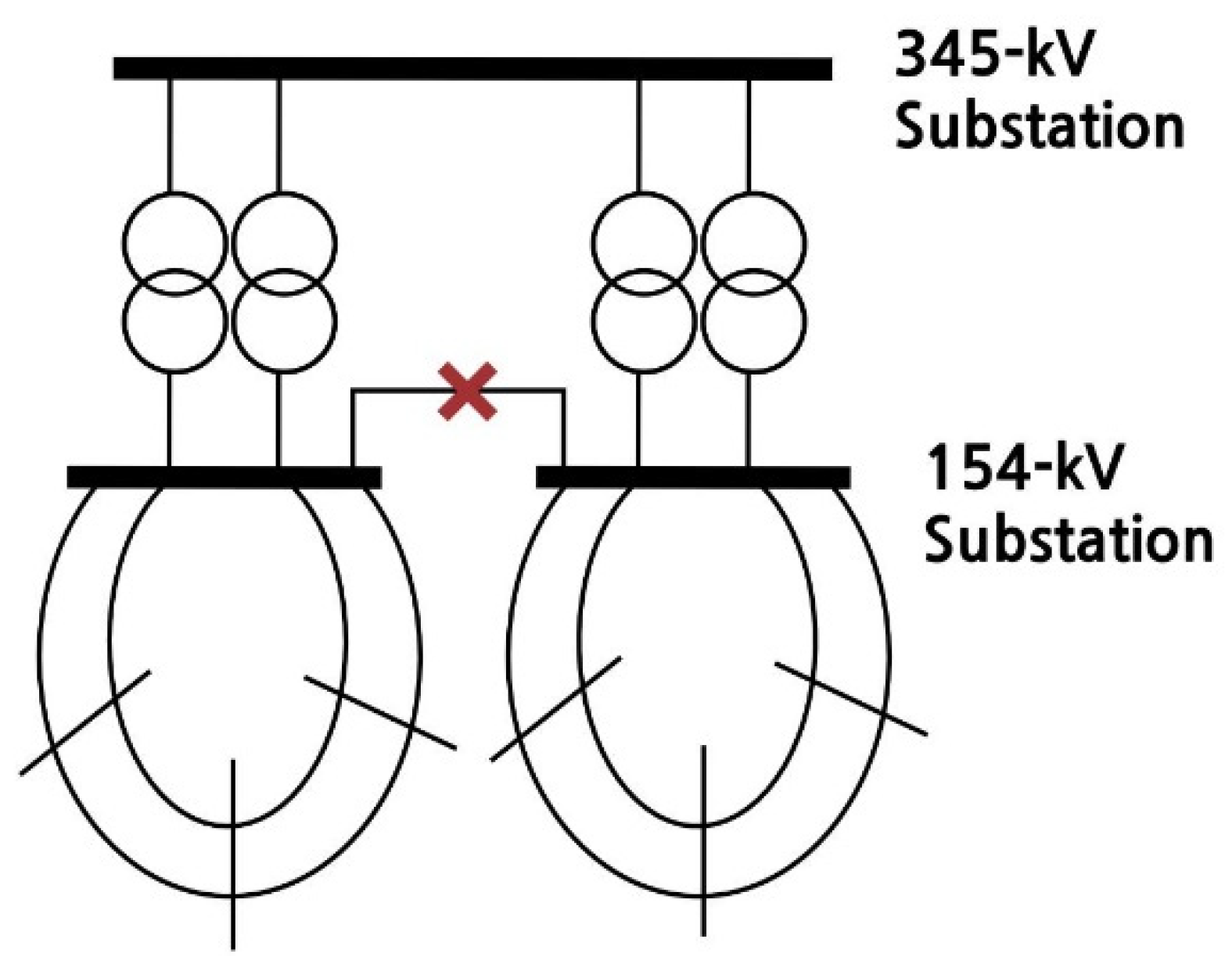
Before establishing a plan to reduce the short-circuit current, it is necessary to examine why the short-circuit current of the busbar is large. Since the magnitude of the short-circuit current is inversely proportional to the magnitude of the impedance, in general, the maximum short-circuit current occurs at the voltage level where the transmission line is the highest. In the case of the KEPCO system, the highest short-circuit current occurs at a voltage level of 154 kV. Considering the inflow path of the short-circuit current in the 154 kV bus, the short-circuit current flowing through the transformer at the upper voltage level of 345 kV is the highest in the situation where the short-circuit current is generally high. Therefore, to reduce the short-circuit current, it is important to separate the 345 kV/154 kV transformer connected by separating the 154 kV bus. For example, if there are four 345 kV/154 kV transformers, the 154 kV bus is divided into two buses, and two transformers are connected to reduce the short-circuit current flowing into each 154 kV bus.
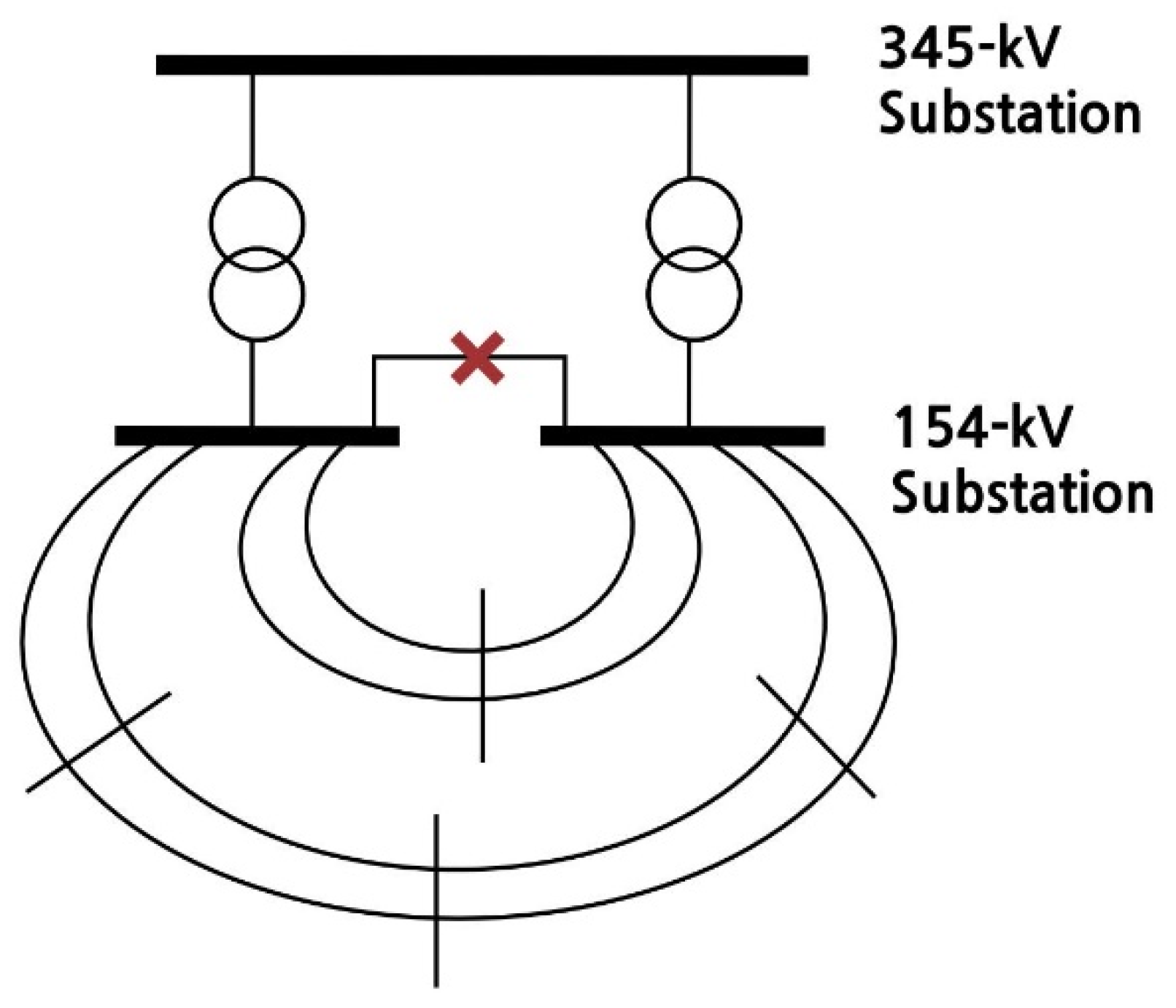
When the transformer is separated in this manner, whether the transformer is overloaded must be considered. Because the transformer is split into individual busbars, the total amount of power that can be handled must be sufficient even if one transformer fails. This is a matter specified in the Korean reliability notice and means that it should be performed without any problem for N-1 failure. To satisfy this requirement, the capacity of the transformer should be sufficient for the existing power consumption. If the capacity of the transformer is sufficient, the short-circuit current can be further reduced by splitting the two buses and independently configuring the 154 kV voltage level. However, if this is not sufficient, it should be configured so that there is no problem by connecting the rear end to a 154 kV level transmission line, because it may violate the reliability notice if the transformer fails. These details are summarized in Figure 1 and Figure 2.
In the case of Figure 1, because the transformer capacity is sufficient, the 154 kV subsystem is independently configured to block the additional inflow path of the short-circuit current, significantly reducing the short-circuit current. Additionally, even if one transformer fails, the reliability notice is not violated, because the stability of the system can be maintained as is. Therefore, in this case, a method for reducing the short-circuit current of the system is selected by additionally implementing a line separation method at an appropriate location so that the lower stage is not connected.
In the case of Figure 2, because the transformer capacity is insufficient, if the 154 kV subsystem is configured independently and one transformer fails, the reliability notice may be violated. Therefore, in this case, the lower end is connected to maintain the stability of the system. In the case of performing busbar separation in this manner, the degree of reduction of the short-circuit current is limited, because additional line separation is not performed.
2.1.2. Line Separation Method
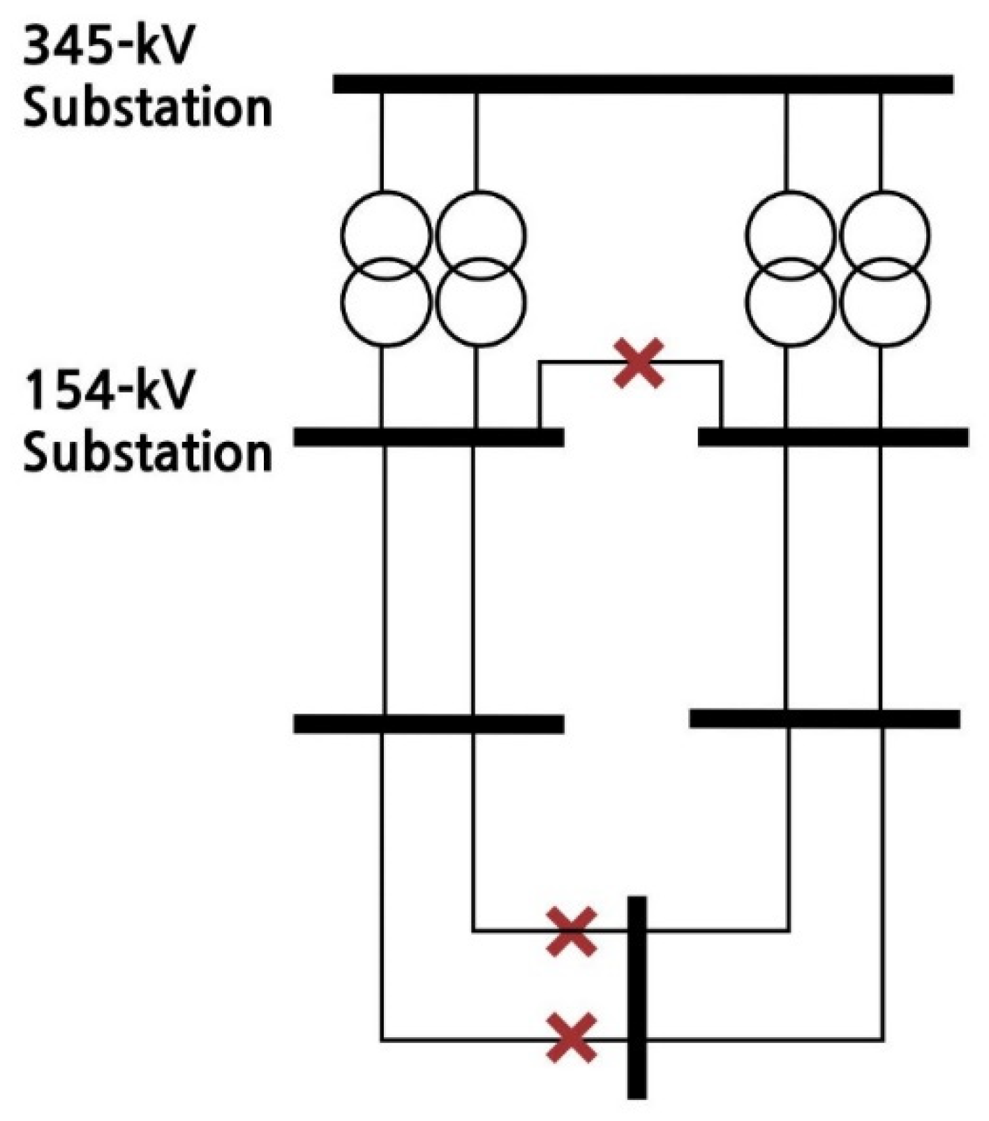
The line separation method is effective for reducing the short-circuit current of the busbar; however, because it cuts the line, there is a risk of reducing the stability. Additionally, it may cause transformer overload and line overload, thereby violating the reliability notice. Therefore, the line separation method should be implemented to the minimum extent, and the method is effective when used in conjunction with the transformer separation method. If there is no problem with the capacity of the transformer, a method should be selected that maximally reduces the short-circuit current by separating the bus line where the short-circuit current is the highest at the lower end and configuring the system independently, and the method should be set as a chromosome group. This concept is illustrated in Figure 3.
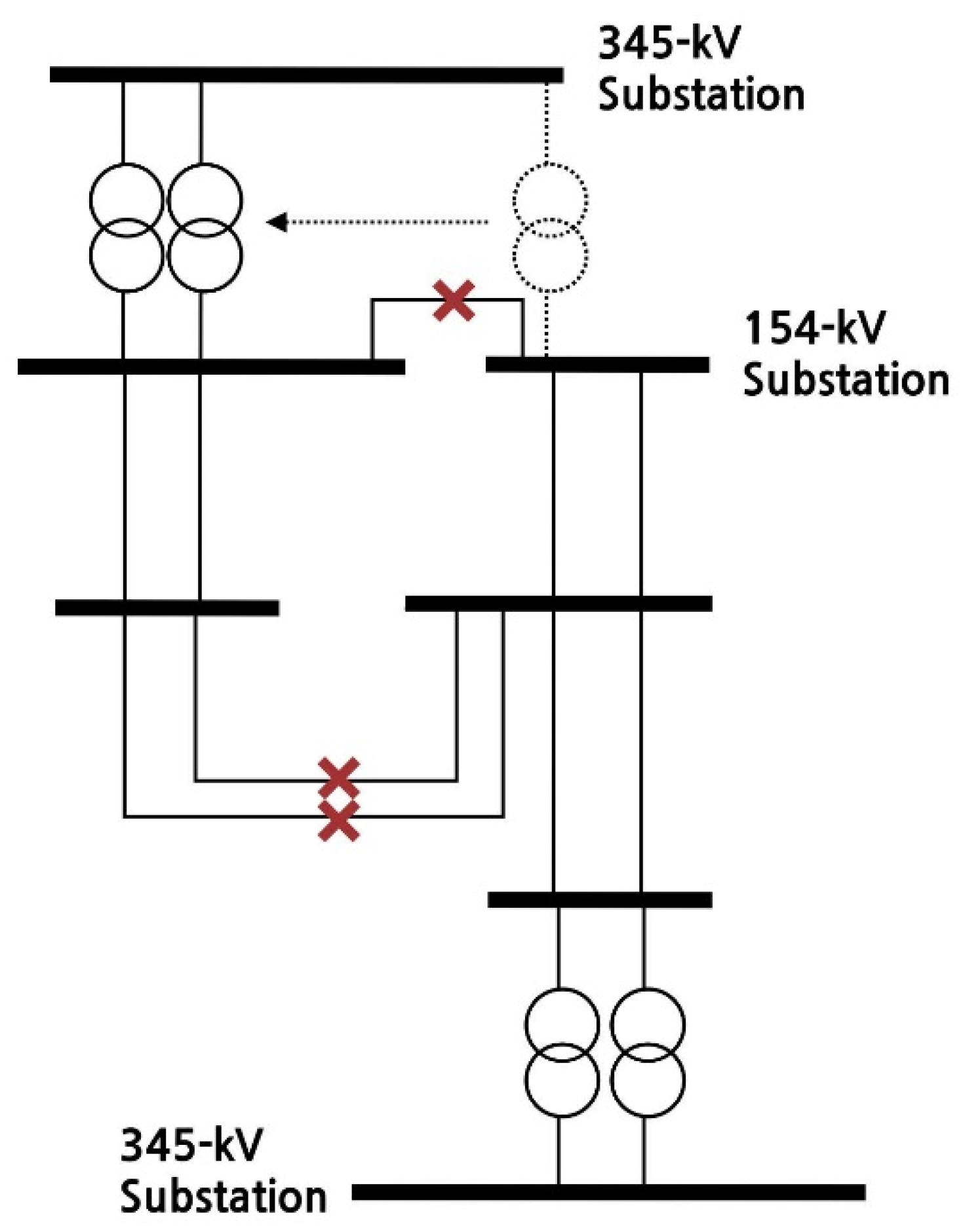
Figure 4 shows the line separation method with an insufficient transformer capacity. The transformer is driven to one side while performing busbar separation, and the line is separated at the lower stage so that each becomes two independent systema; at the same time, these systems are configured so as not to violate the power system reliability notice.
The overall concept of the busbar and line separation methods is shown in Figure 5. In the case of performing the separation as follows, it is possible to ensure the system stability in accordance with the reliability notice while significantly reducing the short-circuit current. Using this method, the mother bar and line that could be separated from the lineage are selected as a chromosome group. A limited number of cases of bus and line separation are used for the chromosome population, increasing the convergence probability of the GP algorithm and reducing the amount of time needed to find the optimal solution.
2.1.3. Chromosome Population Generation
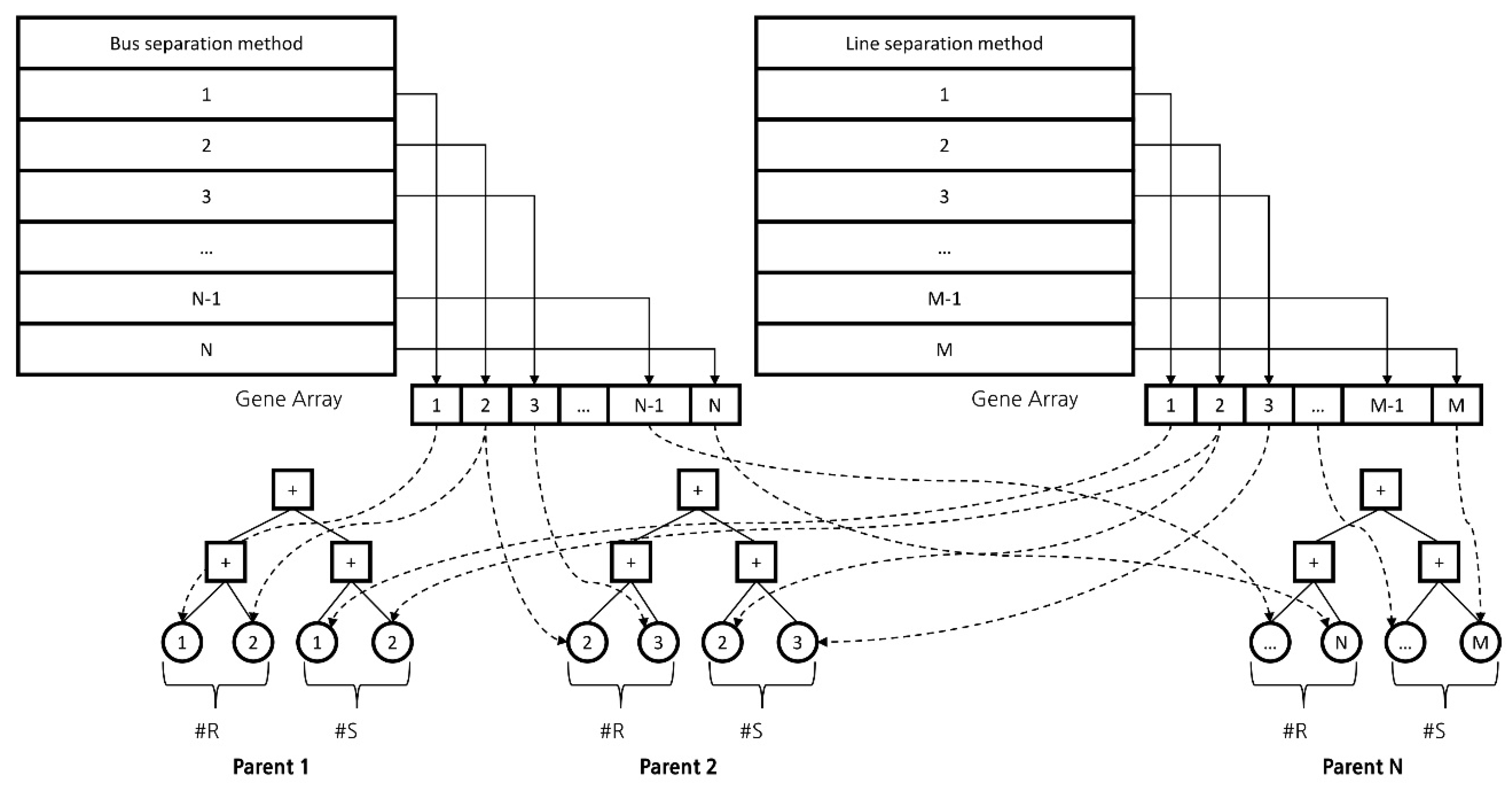
The aforementioned bus and line separation methods are listed, and from these, R busbar separation methods and S line separation methods are selected. One parent chromosome with the R + S separation method is then generated. The busbar separation method and line separation method are each assumed to constitute one gene (which is expressed as an array), and then R busbar separation genes and S line separation genes are randomly selected to generate the chromosome, and the number of parent chromosomes is determined by the number of populations. Figure 6 shows the process of expressing the busbar separation methods and line separation methods as an array, selecting R + S genes, and generating the parent chromosome.
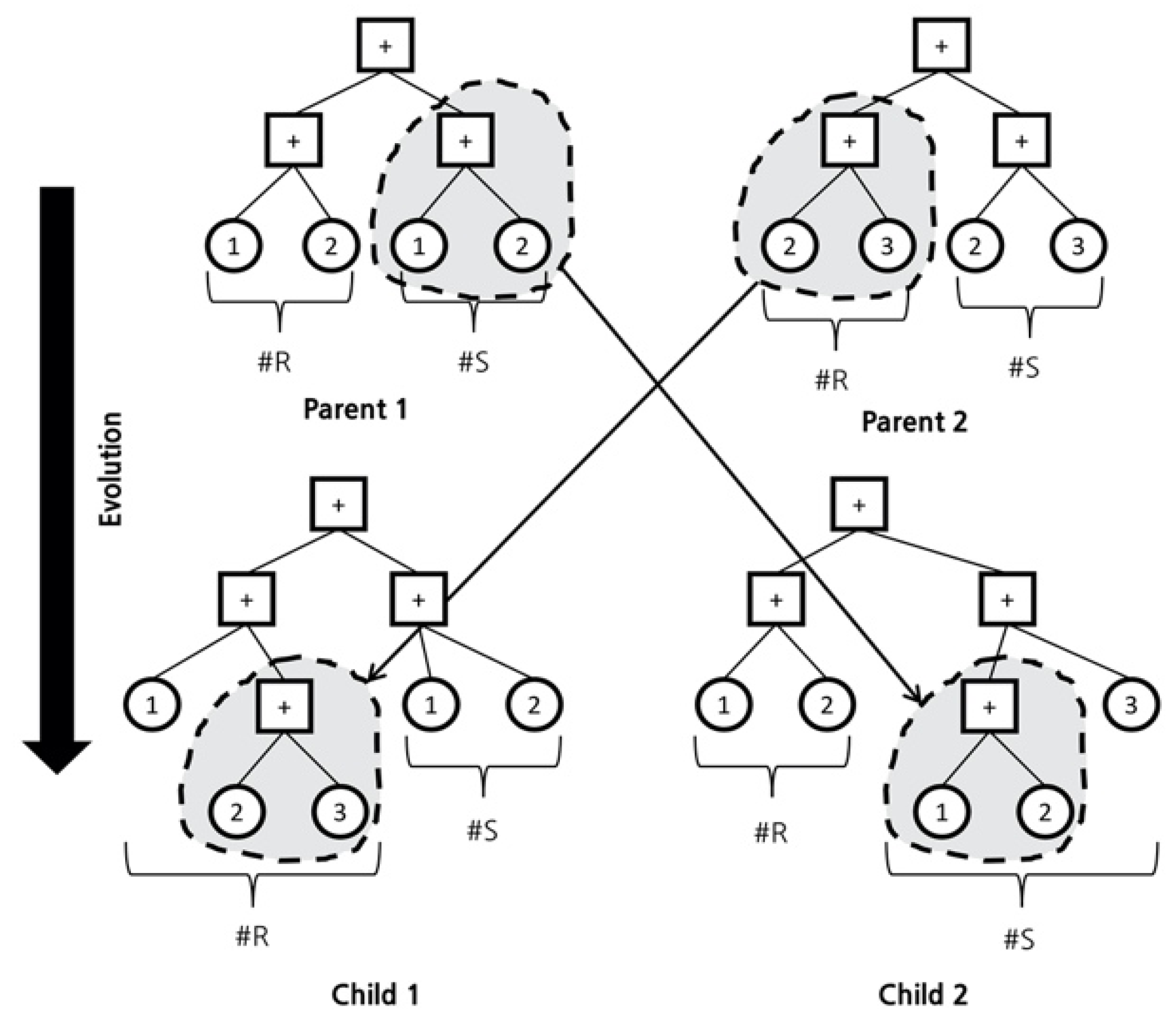
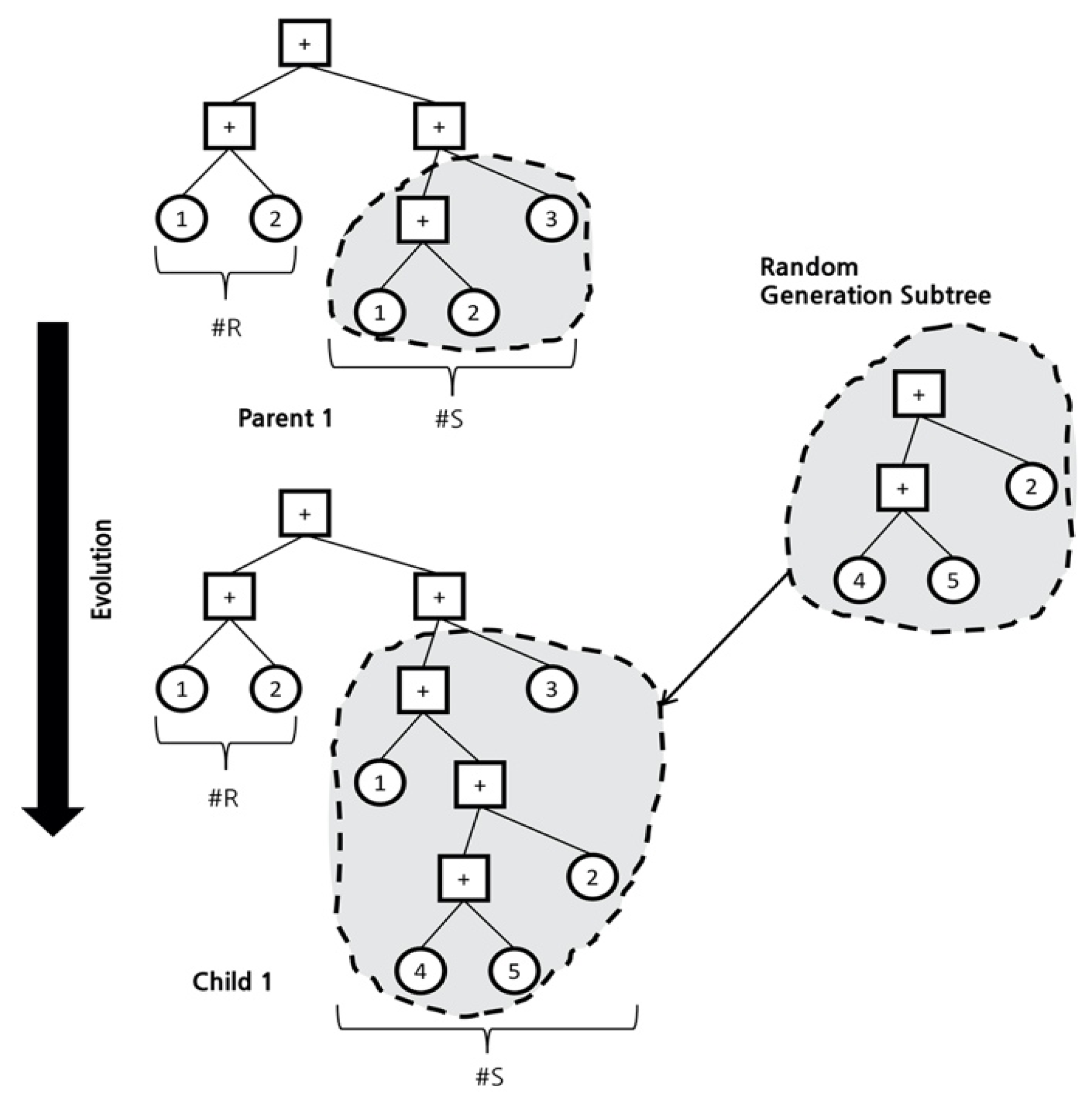
In GP, the operation with crossover or mutation is performed on the parent chromosomes to generate a new chromosome. Chromosomes of the same length may be created; although, in some cases, chromosomes of different lengths are generated. Figure 7 shows the process of generating a new chromosome by crossing two parent chromosomes, and Figure 8 shows the process of creating a new mutation by adding a random chromosome to a parent chromosome. By combining these two processes, chromosomes of various new forms can be created, among which the most ideal form is obtained as the optimization result. To obtain the ideal form, a fitness function is used to obtain the optimal results.
2.2. Fitness Function
To determine whether the selected chromosome represents the optimal method for reducing short-circuit current, it is assessed using the fitness function. First, as the selected chromosome must correspond to a method that reduces the short-circuit current to the greatest extent possible, the number of buses (Tn) exceeding the breaker capacity for this method must be as small as possible. Additionally, after the busbar separation and line separation of this chromosome are performed, the number of overloaded lines and transformers (Un) must be as small as possible. The bus and line separation methods themselves are factors that degrade the stability of the power system; thus, a smaller number of genes constituting the chromosome is better. Accordingly, a smaller number of busbar separation methods (R) and line separation methods (S) is better. These four variables are included in the fitness function, and weights are added to ensure optimal convergence:
where Tn represents the number of buses with short-circuit current exceeding breaker capacity, Un represents the number of overloaded lines and transformers, R represents the number of busbar separation methods, and S represents the number of line separation methods.
According to (1), a larger number of buses in which the short-circuit current exceeds the breaker capacity corresponds to a larger denominator and a lower fitness value. As the number of overloaded lines and transformers increases, the denominator increases, reducing the fitness. The number of overloaded lines and transformers must be close to zero to comply with the reliability standards. However, the number of buses exceeding the breaker capacity need not be close to zero, as they can be replaced in the future using methods such as the current-limiting reactor or BTB HVDC. Furthermore, although it is better to have a smaller number of busbar separation methods and line separation methods, it is impossible to reduce them to a number close to zero with existing grid operation methods. Therefore, numbers similar to those of the existing bus and line separation methods used in grid operations should be set. If a range for the number of bus and line separation methods is not set, an excessive number of iterations will be performed during optimization. Hence, a range similar to that of existing grid operation methods should be set while ensuring convergence to the optimal result.
Using the fitness Function (1), a GA is executed that minimizes the number of buses in which the short-circuit current exceeds the breaker capacity, minimizes the number of bus and line separation methods, and does not overload the lines. As the ranges for Tn, Un, R, and S affect the convergence to the optimal result, appropriate values should be selected; this is discussed below.
3. Applied System and Simulation
3.1. Applied System and Simulation Conditions
In the system analysis to minimize the points exceeding the breaker capacity, for verifying the effectiveness of the proposed method, the power-system data for 2018–2025 are used. In the case of a 345 kV busbar (a 345 kV bus), the minimum busbar separation and line separation are performed in advance so that there is no point at which the short-circuit current of the 345 kV busbar is exceeded. Additionally, for short-circuit current analysis, all generators included in the power system are turned on, and the generator impedance is set such that the short-circuit current is as high as possible using sub-transient impedance.
According to the results of various simulations, it is necessary to set the range for each variable to obtain a meaningful optimization result that can be used in the operation of an actual power system. First, in the case of Tn, which corresponds to the number of busbars exceeding the breaker capacity of the short-circuit current, if there is even one excess part of the breaker, the reliability notice is violated; thus, Tn must be zero. Additionally, if the number of overload lines and transformers (Un) exceeds one, the reliability notice is violated; thus, Un must be zero. For R and S, i.e., the numbers of bus and line separations, respectively, a range beginning from one would require too many simulations. A suitable range is therefore determined by referring to the numbers of bus and line separations from the actual operational data. According to the actual results, for 154 kV buses, the number of busbar separations ranges from 37 to 44, and the number of line separations ranges from 64 to 80. In the analysis, using a busbar separation range of ±20, the number of busbar separations R was set as 30–70, and the number of line separations S was set as 40–80. Simulations were then conducted under these conditions. The variable ranges were defined as follows:
The GP was therefore configured with Tn and Un of zero and the minimum values for R and S, and optimization was performed.
These simulations were classified into two categories: (a) the whole gene method in which all chromosomes belonging to the entire grid are used for the bus and line separation methods and (b) the selected gene method in which chromosomes are selectively generated, as described in Section 2.1.1 and Section 2.1.2. Table 1 presents the number of chromosomes that can be participated in each method.
3.2. Simulation Results
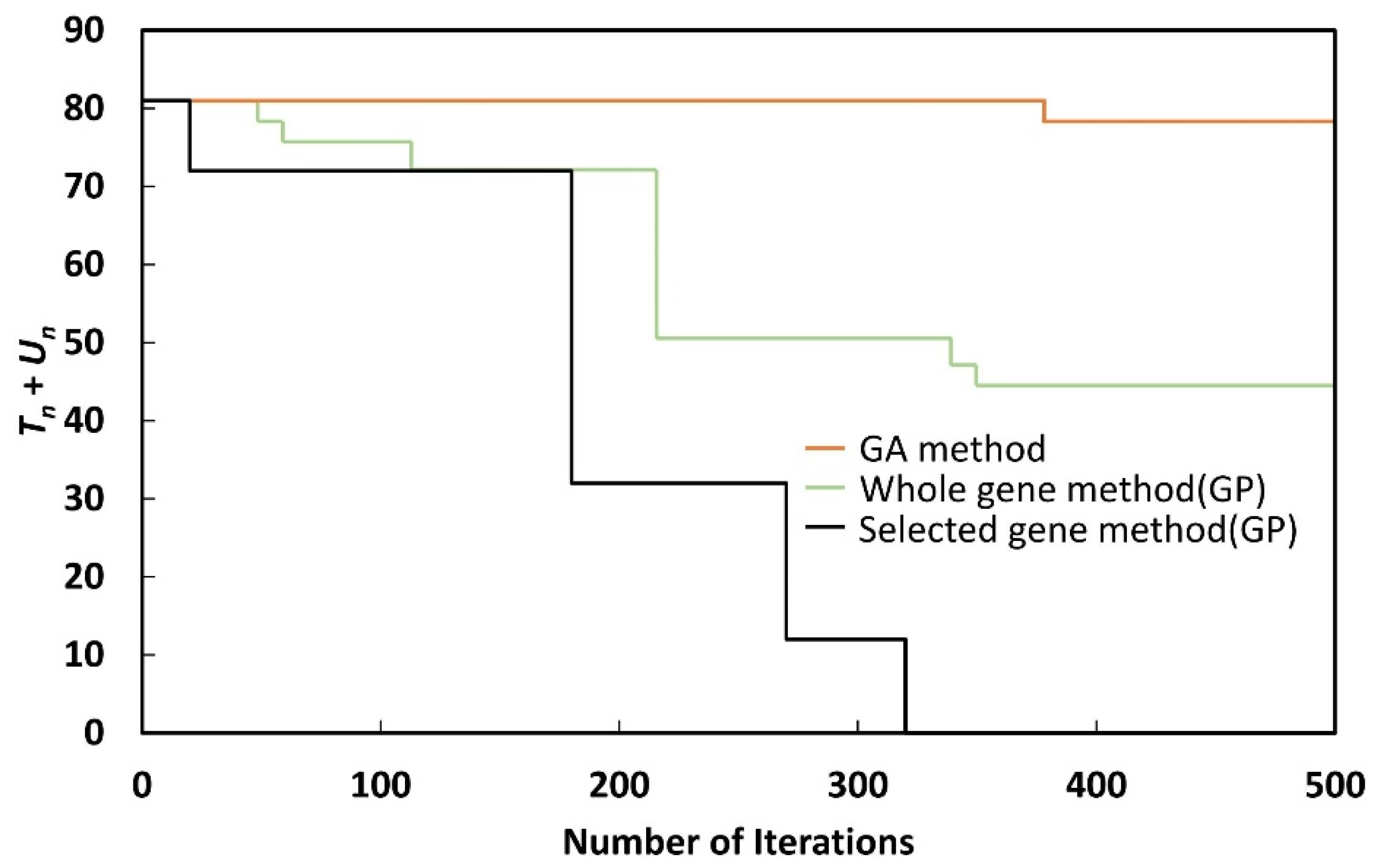
A crossover rate of 95% and a mutation rate of 1% were applied in the simulations, with iterations performed for up to 500 generations. Eight years of power-system data (2018–2025) were simulated, and the conditions of the fitness function were checked at every iteration to obtain the optimal results.
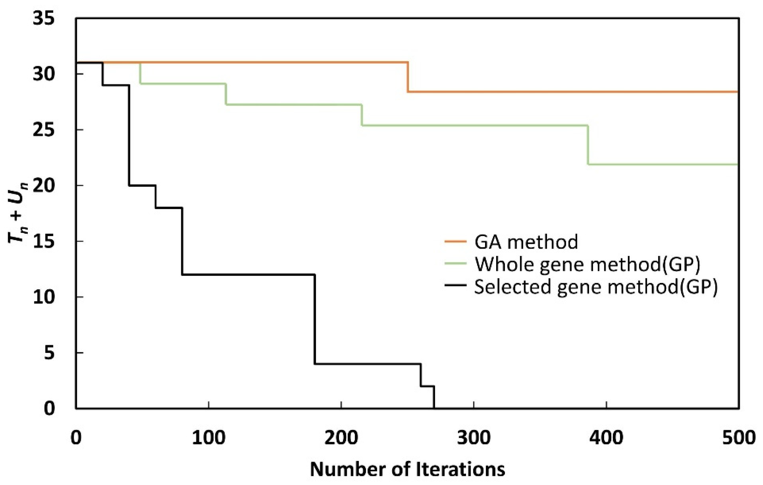
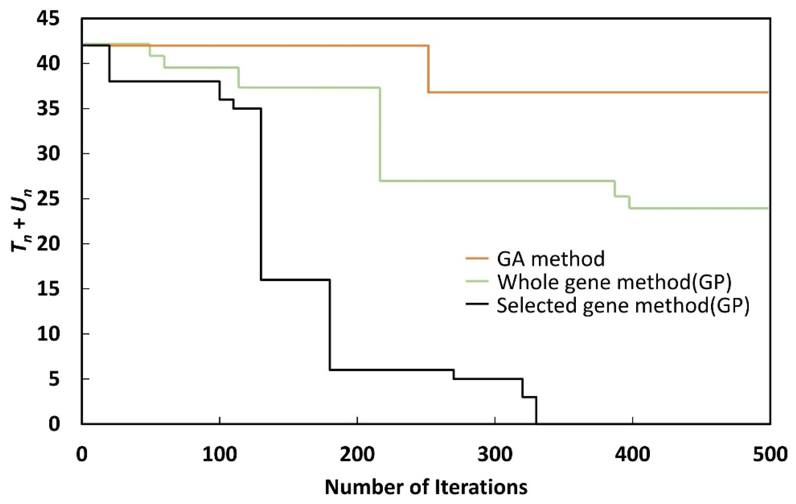
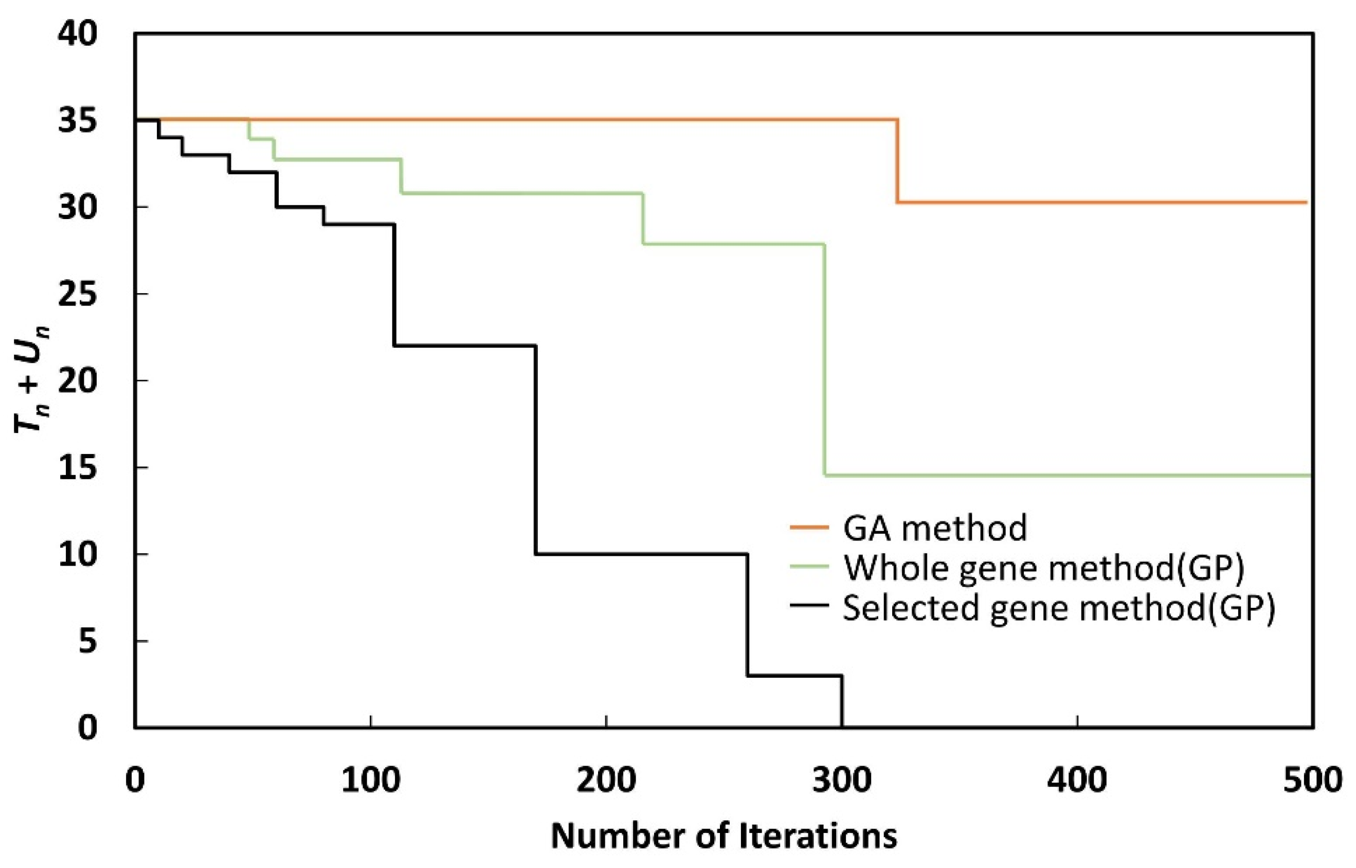
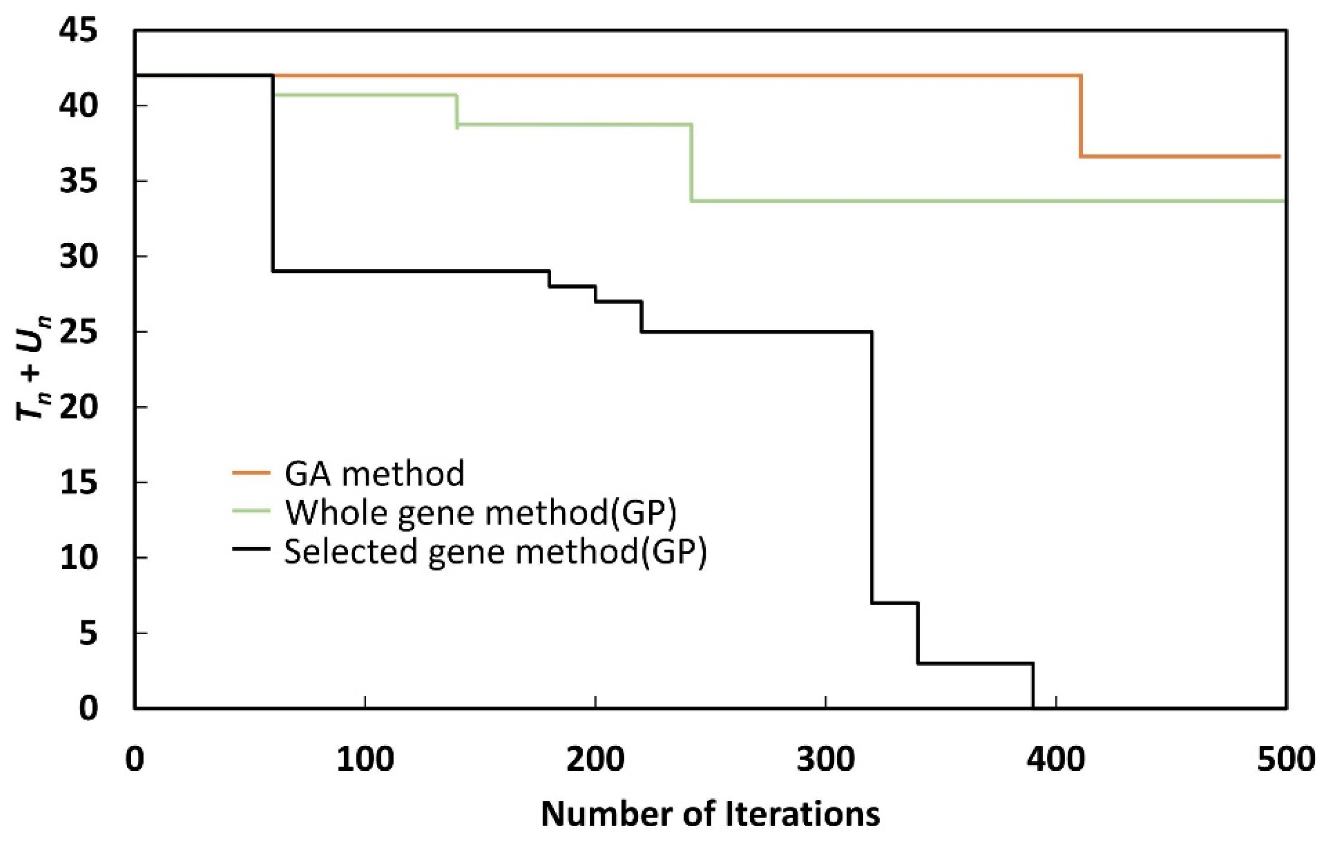
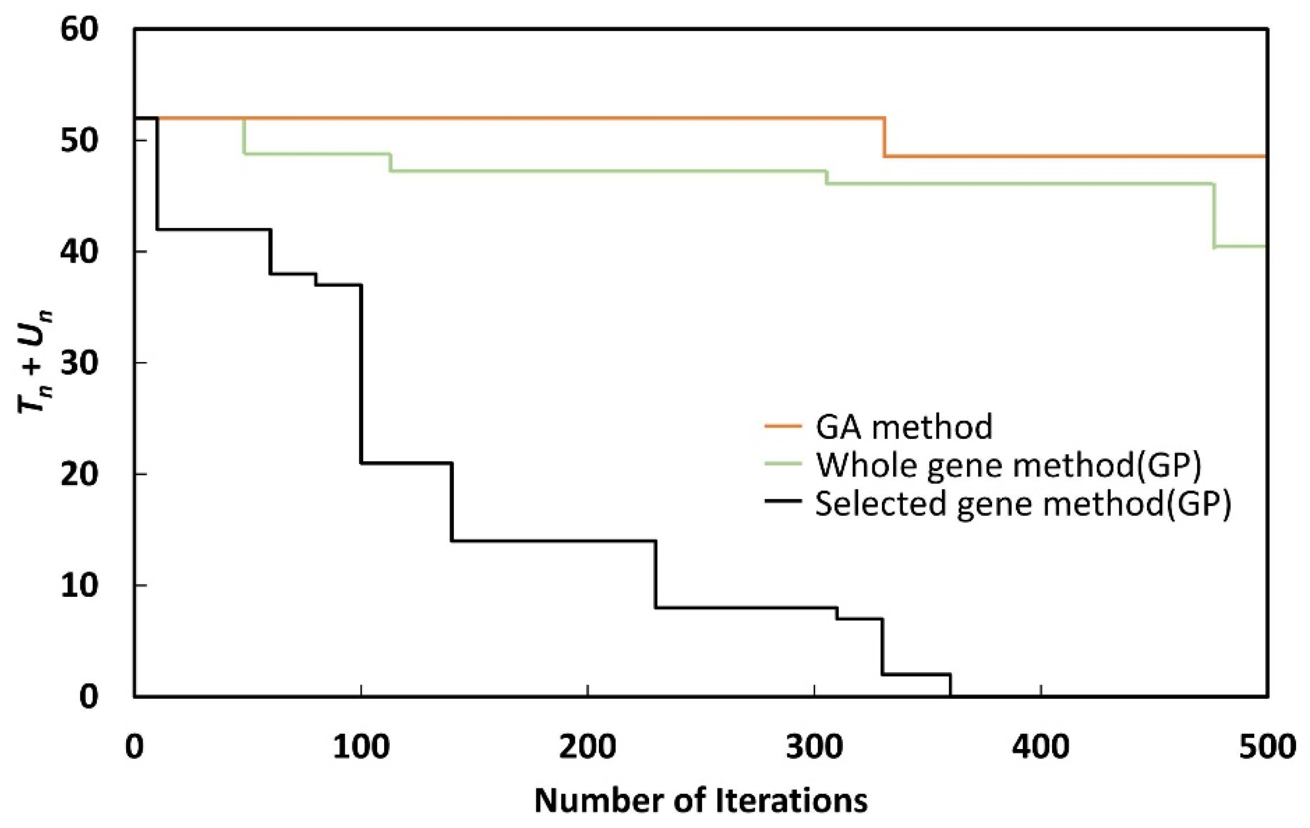
As shown in Figure 9, Figure 10, Figure 11, Figure 12, Figure 13, Figure 14, Figure 15 and Figure 16, although Tn + Un could be reduced to zero with the selected gene method, when the whole gene method or GA method was used, Tn + Un could not be reduced to zero, even after 500 generations. Although the whole gene method could reduce Tn + Un to zero by performing more iterations, the nature of GP makes this undesirable, as the process takes a long time.
Table 2 presents the numbers of busbar separation methods (R) and line separation methods (S). For each year, the optimization results with R and S values ranging from 56 to 69 were obtained. These values exceed the actual operation data, because the power grid grew in size.
There are numerous ways to reduce the short-circuit current to reduce the number of busbars exceeding the breaker capacity, and to identify the optimal method, it is necessary to manually perform numerous simulations. However, as suggested in this paper, if the formula is defined in accordance with GP and the number of chromosomes is configured and limited by the methods that are possible in the lineage, an optimized result can be obtained via GP. If the GP is systematically structured to reduce the short-circuit current, an effective short-circuit current reduction plan can be obtained in the 9th power-system supply and demand plan in the future, which can be used continuously.
4. Conclusions
A GP-based optimization method is proposed for systematically selecting the optimal method to reduce the short-circuit current in a power system by organizing the busbar separation method and the line separation method, which are the traditional methods for reducing the short-circuit current. By variably defining the number of busbar separation methods and the number of line separation methods, which correspond to the chromosome length, in contrast to the GA method, and performing optimization through these methods, it was possible to identify the optimal short-circuit current reduction method among numerous methods. A systematic technique for selecting a method that can be implemented in the system among numerous busbar separation methods and line separation methods was presented. By reducing the number of chromosome groups, the GP optimization results can be obtained more quickly. GP is an effective optimization method for obtaining an ideal solution-free method. Because the chromosome length is variable, GP is suitable for reducing the short-circuit current using the busbar separation method and the line separation method. In the future, if the fitness function of GP is further improved and a more specific and limited method is used for selecting chromosomes, the performance of the GP can be improved. This will be useful for creating a power-system supply and demand plan database that will be continuously used in the future.
Author Contributions
Formal analysis, D.S.; Methodology, S.H.; Project administration, S.H.; Validation, D.S.; Visualization, D.S.; Writing—original draft, D.S.; Writing—review & editing, S.H. All authors have read and agreed to the published version of the manuscript.
Funding
This work was supported by the Korea Institute of Energy Technology Evaluation and Planning (KETEP), the Ministry of Trade, Industry & Energy (MOTIE) of the Republic of Korea (No. 20214000000060), and the Korea Electric Power Corporation (No. R21XO01-31).
Institutional Review Board Statement
Not applicable.
Informed Consent Statement
Not applicable.
Conflicts of Interest
The authors declare no conflict of interest.
References
- Ministry of Trade, Industry and Energy. The 8th Basic Plan for Power Supply; Ministry of Trade, Industry and Energy: Seoul, Korea, 2017.
- Han, S.; Ha, Y. A study on the setting of fault current limit for KEPCO’s future system. In Proceedings of the International Council on Electrical Engineering Conference, Hong Kong, China, 2–6 July 2019. [Google Scholar]
- Wang, L.; Chiang, H. Toward online bus-bar splitting for increasing load margins to static stability limit. IEEE Trans. Power Syst. 2017, 32, 3715–3725. [Google Scholar] [CrossRef]
- Shen, Z.; Tang, Y.; Chiang, H. Toward online line switching methodology for relieving power system overloads. In Proceedings of the IEEE Power & Energy Society General Meeting (PESGM), Atlanta, GA, USA, 4–8 August 2019; pp. 1–5. [Google Scholar]
- Wang, L.; Chiang, H. Group-based line switching for enhancing contingency-constrained static voltage stability. IEEE Trans. Power Syst. 2020, 35, 1489–1498. [Google Scholar] [CrossRef]
- Koeppi, G.; Blahous, L.; Hager, H. Short-circuit current partitioning in HV substations in ring-bus arrangement with redundancy. IEEE Trans. Power Appar. Syst. 1984, PAS-103, 2651–2658. [Google Scholar] [CrossRef]
- Koeppl, G.; Stepinski, B.; Frey, H.; Kolbe, W. The crossed-ring arrangement a new concept for H.V. switchgear installations. IEEE Trans. Power Appar. Syst. 1983, PAS-102, 355–363. [Google Scholar] [CrossRef]
- Barkan, P.J.; Beehler, E.; Reckleff, J. Breaker contact behavior with rapid sequential switching above fault rating. IEEE Trans. Power Appar. Syst. 1983, PAS-102, 2476–2485. [Google Scholar] [CrossRef]
- Hamidi, M.E.; Chabanloo, R.M. Optimal allocation of distributed generation with optimal sizing of fault current limiter to reduce the impact on distribution networks using NSGA-II. IEEE Syst. J. 2019, 13, 1714–1724. [Google Scholar] [CrossRef]
- Yang, H.; Tang, W.; Lubicki, P.R. Placement of fault current limiters in a power system through a two-stage optimization approach. IEEE Trans. Power Syst. 2018, 33, 131–140. [Google Scholar] [CrossRef]
- Lee, B.W.; Sim, J.K.; Park, B.; Oh, I.S. Practical application issues of superconducting fault current limiters for electric power systems. IEEE Trans. Appl. Superconduct. 2008, 18, 620–623. [Google Scholar] [CrossRef]
- Kim, Y.; Jo, H.; Joo, S. Analysis of impacts of superconducting fault current limiter (SFCL) placement on distributed generation (DG) expansion. IEEE Trans. Appl. Superconduct. 2016, 26, 1–5. [Google Scholar] [CrossRef]
- Jo, H.; Joo, S. Superconducting fault current limiter placement for power system protection using the minimax regret criterion. IEEE Trans. Appl. Superconduct. 2015, 25, 1–5. [Google Scholar] [CrossRef]
- El Moursi, M.S.; Hegazy, R. Novel technique for reducing the high fault currents and enhancing the security of ADWEA power system. IEEE Trans. Power Syst. 2013, 28, 140–148. [Google Scholar] [CrossRef]
- Tosato, F.; Quaia, S. Reducing voltage sags through fault current limitation. IEEE Trans. Power Deliv. 2001, 16, 12–17. [Google Scholar] [CrossRef]
- Esmaeili, A.; Esmaeili, S.; Hojabri, H. Short-circuit level control through a multi-objective feeder reconfiguration using fault current limiters in the presence of distributed generations. IET Gener. Transm. Distrib. 2016, 10, 3458–3469. [Google Scholar] [CrossRef]
- Smith, L.M. A practical approach in substation capacitor bank applications to calculating, limiting, and reducing the effects of transient currents. IEEE Trans. Ind. Appl. 1995, 31, 721–724. [Google Scholar] [CrossRef]
- Ha, Y.G.; Jeon, W.J.; Chang, B.H. A study on the effects of BTB HVDC for fault current reduction applied metropolitan area in KEPCO Grid. In Proceedings of the 8th International Conference on Power Electronics—ECCE Asia, Jeju, Korea, 29 May–2 June 2011; pp. 2962–2969. [Google Scholar]
- Labios, R.; Song, H. Determining the placement of BTB converters for fault current reduction in a power system by using a hybrid GA-Tabu search method. In Proceedings of the Joint 7th International Conference on Soft Computing and Intelligent Systems (SCIS), Kitakyushu, Japan, 3–6 December 2014; pp. 5–8. [Google Scholar]
- Xi, X.; Gao, X.; Huang, W.; Li, S.; Zhao, Y.; Lv, C. Application analysis of resistor superconducting fault current limiter in MMC-HVDC system. In Proceedings of the IEEE Sustainable Power and Energy Conference (iSPEC), Beijing, China, 20–24 November 2019; pp. 2260–2264. [Google Scholar]
- Yoon, M.; Park, J.; Jang, G. A study of HVDC installation in Korean capital region power system. In Proceedings of the IEEE Power and Energy Society General Meeting, San Diego, CA, USA, 22–26 July 2012; pp. 1–5. [Google Scholar]
- Koza, J.R. Genetic Programming: On the Programming of Computers by Natural Selection; MIT Press: Cambridge, MA, USA, 1992. [Google Scholar]
- Koza, J.R.; Bennet, F.H.; Andre, D.; Keane, M.A.; Dunlap, F. Automated synthesis of analog electrical circuits by means of genetic programming. IEEE Trans. Evol. Comput. 1997, 1, 109–128. [Google Scholar] [CrossRef] [Green Version]
- Walker, J.A.; Miller, J.F. The automatic acquisition, evolution and reuse of modules in cartesian genetic programming. IEEE Trans. Evol. Comput. 2008, 12, 397–417. [Google Scholar] [CrossRef]
- Huynh, Q.N.; Chand, S.; Singh, H.K.; Ray, T. Genetic programming with mixed-integer linear programming-based library search. IEEE Trans. Evol. Comput. 2018, 22, 733–747. [Google Scholar] [CrossRef]
- Yan, W.; Lu, S.; Yu, D.C. A novel optimal reactive power dispatch method based on an improved hybrid evolutionary programming technique. IEEE Trans. Power Syst. 2004, 19, 913–918. [Google Scholar] [CrossRef]
- Goldberg, D.E. Genetic Algorithms in Search Optimization and Machine Learning; Addison-Wesley: Pittsburgh, PA, USA, 1989. [Google Scholar]
- Sheng, W.; Liu, K.; Liu, Y.; Meng, X.; Li, Y. Optimal placement and sizing of distributed generation via an improved nondominated sorting genetic algorithm II. IEEE Trans. Power Deliv. 2015, 30, 569–578. [Google Scholar] [CrossRef]
- Song, M.; Kim, H.; Lee, B. A study on selecting the optimal location of BTB HVDC for reducing fault current in metropolitan regions based on genetic algorithm using python. Trans. Korean Inst. Electr. Eng. 2017, 66, 1163–1171. [Google Scholar]
- Cheng, J.; Yang, Y. Application of hybrid genetic algorithm in optimization formula system. In Proceedings of the 2nd International Conference on Education Technology and Computer (ICETC), Shanghai, China, 22–24 June 2010; Volume 4, pp. 130–134. [Google Scholar]
Figure 1.
Busbar separation method with a sufficient transformer capacity.

Figure 2.
Busbar separation method with an insufficient transformer capacity.

Figure 3.
Line separation method with a sufficient transformer capacity.

Figure 4.
Line separation method with an insufficient transformer capacity.

Figure 5.
Bus and line separation method for reducing the short-circuit current.

Figure 6.
Gene array configuration plan with the bus and line separation methods in GP.

Figure 7.
Concept of the crossover method in GP.

Figure 8.
Concept of the mutation method in GP.

Figure 9.
GP results for the minimized fitness function (2018).

Figure 10.
GP results for the minimized fitness function (2019).

Figure 11.
GP results for the minimized fitness function (2020).

Figure 12.
GP results for the minimized fitness function (2021).

Figure 13.
GP results for the minimized fitness function (2022).

Figure 14.
GP results for the minimized fitness function (2023).

Figure 15.
GP results for the minimized fitness function (2024).

Figure 16.
GP results for the minimized fitness function (2025).


Table 1.
Number of chromosomes participating in each method.
| Year | Selected Gene Method | Whole Gene Method | ||
|---|---|---|---|---|
| No. of Busbar Separation Methods | No. of Line Separation Methods | No. of Busbar Separation Methods | No. of Line Separation Methods | |
| 2018 | 425 | 622 | 1210 | 2780 |
| 2019 | 425 | 623 | 1210 | 2782 |
| 2020 | 426 | 624 | 1213 | 2784 |
| 2021 | 426 | 625 | 1216 | 2788 |
| 2022 | 427 | 628 | 1217 | 2792 |
| 2023 | 428 | 629 | 1220 | 2801 |
| 2024 | 428 | 629 | 1222 | 2805 |
| 2025 | 429 | 630 | 1225 | 2813 |
Table 2.
Final results for R and S.
| Year | Number of Busbar Separation Methods | Number of Line Separation Methods |
|---|---|---|
| 2018 | 60 | 56 |
| 2019 | 58 | 59 |
| 2020 | 60 | 56 |
| 2021 | 64 | 64 |
| 2022 | 64 | 64 |
| 2023 | 69 | 63 |
| 2024 | 68 | 63 |
| 2025 | 66 | 64 |
Publisher’s Note: MDPI stays neutral with regard to jurisdictional claims in published maps and institutional affiliations. |
© 2022 by the authors. Licensee MDPI, Basel, Switzerland. This article is an open access article distributed under the terms and conditions of the Creative Commons Attribution (CC BY) license (https://creativecommons.org/licenses/by/4.0/).
Share and Cite
MDPI and ACS Style
Son, D.; Han, S. Development of Bus and Line Control Method for Short-Circuit Current Reduction Using Genetic Programming. Energies 2022, 15, 678. https://doi.org/10.3390/en15030678
AMA Style
Son D, Han S. Development of Bus and Line Control Method for Short-Circuit Current Reduction Using Genetic Programming. Energies. 2022; 15(3):678. https://doi.org/10.3390/en15030678
Chicago/Turabian StyleSon, Dabin, and Sangwook Han. 2022. "Development of Bus and Line Control Method for Short-Circuit Current Reduction Using Genetic Programming" Energies 15, no. 3: 678. https://doi.org/10.3390/en15030678
Note that from the first issue of 2016, this journal uses article numbers instead of page numbers. See further details here.